MIRA-35 Cloud Radar
System Description
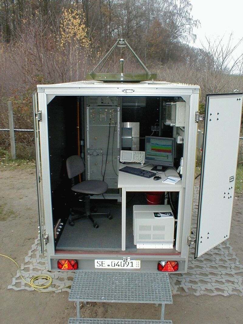
MIRA-35 is a Ka-band radar for detecting clouds, fog, and precipitation in the atmosphere. It is typically operating at 35.1 GHz or a wavelength of 8.55 mm.
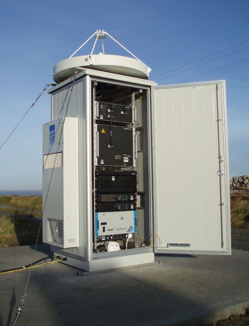
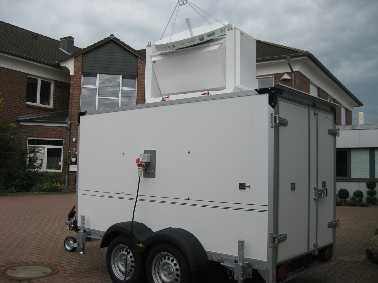
In its standard configuration it has a vertically pointing 1 m antenna which is mounted on an enclosed trailer or an outdoor enclosure.
It is also available with a scanning unit for making azimuth and elevation scans. In the scanning configuration the antenna and the radar electronics are mounted on a two axis positioner.
Also a lightweight configuration for airborne installation is available which fits to a 19 inch rack with a height of 14 U (including PC).
Polarization Feature
MIRA-35
transmits with one single linear polarization and receives the
co-polarized and optionally the cross-polarized signal. For the cross
polarized signal a separate receiver is used so that reflectivity and
LDR (the ration between the reflectivity of the cross and the co
channel) is provided simultaneously. The cross channel is very useful
for the target classification. The radar can also be configured for
Simultaneously Transmitting And Receiving H- and V-polarized signals
(STAR).
Transmitter
The transmitted signal is generated by a magnetron providing 30 kW pulse power at pulse durations between 100 ns and 400 ns. Due to the high pulse power a fine range resolution is possible without pulse compression. When operated continuously these magnetrons have a very long life time.
Receiver
The total noise figure of the receiver, including waveguide-, circulator-, and TR-switch-losses is 6.3 dB. The image band noise is rejected at each frequency conversion stage. The minimum detectable reflectivity factor is -52.4 dBZ at range = 5 km, PRF = 5 kHz, FFT size = 256, number of coherent averages = 200 (i.e. integration time = 10 s), and a pulse length of 200 ns (30 m).
Doppler Technique
As each pulse transmitted by the magnetron has a random phase the Doppler capability of MIRA-35 is realized by the "digital coherence on receiver technique": A small fraction of the transmitted signal is coupled into the receiver. From this signal the phase of the transmitted pulse, compared to the local oscillator, is measured. During the rest of the pulse cycle the phase of the transmitted pulse is subtracted from the I-Q-signal. This phase correction is performed by FPGAs after the sampled I-Q-signal was filtered and decomposed to 800 range gates.
Signal Processing
The complete signal processing is implemented by FPGA. The FFT processing and moment estimation of 2*800 range gates can be processed with or without in-coherent averaging. Alternatively, it is possible to save all the spectra or I-Q data on the PCs hard disk and let the PC do the processing.
Calibration
A permanent calibration system is included in the receiver.
A fraction of the transmitted signal is coupled to a thermistor detector in order to monitor the average transmitting power (=peak power x duty cycle). The receiver calibration is derived from two alternative sources:
The receiver noise level is measured at the end of each pulse cycle before the PIN switches which are part of the TR-switch go to the off-state. As the noise figure is very constant and can be measured very precisely, the receiver noise provides a precise receiver calibration with good long term stability. On the other hand, this receiver calibration can only be used when the radar is operated pointing upward and when there is a region at the end of the pulse cycle where no meteorological signal can be expected (i.e. 2 c / PRF > 14 km). Heavy rain also causes a problem for this calibration procedure as radiometric signals increase the noise level by about 1-2 dB.
Also at the end of each pulse cycle, but after the PIN modulators of the TR-switch have gone to the off-state, the signal from a reference noise source is introduced to the input of the 35 GHz low noise amplifier. This noise signal is about 15 dB above thermal noise. It can be used for receiver calibration during airborne operation, during rain and even when the receiver amplification is reduced by automatic gain control in case of heavy rain.
Software for radar operation
A GUI-interface for operating the radar and for making all setting is provided. The radar can as well be operated by scripts and cron-jobs. The radar software is tailored for remote administration and for automatic operation. The radar software is available for windows and Linux. The Linux version is more suitable for remote administration. Each module of the radar electronics (transmitter, receiver, LO frequency control, scanning drive control unit) is equipped with an own microcontroller. These microcontrollers have analog and digital in- and outputs for controlling the operational mode and for providing diagnostic information in case of failures. Each hardware controller is programmed to protect the hardware instantaneously on basis of the measured data even if the radar PC is down. Once per second approximately 50 measured parameters are transmitted to the radar PC. These parameters are saved to a log file which simplifies trouble shooting. These parameters are analyzed continuously by a perl script which can be configured to send e-mail warnings to the radar operator in case any parameter exceeds the expected range.
Software for visualization
Platform independent “Data Clients” are provided for viewing the actually measured radar data. They are launched on the users PC. Then, they connect to the radar PC via network to get the radar data as it is measured.
For visualizing radar data which is saved on the hard disk IDL programs are provided. These IDL programs are used by a command line interface. Therefore, they can also be used for automatic generation of images. The png-images which can be found on this webserver are generated by these IDL-programs.
Software for Target separation and classification
Algorithms for separating multiple peaks from the Doppler spectra and for the classification of these peaks have been and are still developed by METEK. See the Extended Abstract “Target Separation and Classification using Cloud Radar Doppler Spectra” of our contribution to the 33rd Conference on Radar Meteorology for a description of these algorithms.
System Specifications
The following specifications represent typical settings which give an idea of the field of application for the MIRA-35. Other specifications can be selected or provided by design. Please contact METEK if other specifications are needed for your application.
|
Radar Type |
Mono static, pulsed, magnetron transmitter |
|
Frequency |
33–37 GHz depending on local frequency allocation. Standard: 35.1 GHz +/- 100 MHz |
|
Peak Power |
30 kW |
|
Duty Cycle |
max 1:500; typically 1:1000 |
|
Pulse Width |
100, 200, and 400 ns according to 15, 30, and 60 m range resolution |
|
Minimum Height |
100...150 m, full sensitivity above 450 m |
|
Maximum Height |
0.5*c * (1/PRF - 8 μs), due to calibration, typically 28.8 km |
|
Maximum Number of Rage Gates |
2*800 (two polarizations) |
|
Doppler Velocity Resolution |
< 0.02 m/s |
|
Pulse Repetition Frequency (PRF) |
2.5 – 10 kHz according to velocity un-ambiguity of 11 – 42 m/s, typically 5 kHz |
|
FFT Length |
128, 256, 512, 1024 |
|
Minimum Averaging Time |
Moments of instantaneous spectra can be evaluated without skipping samples if NFFT > 128 |
|
Receiver Type |
Digital receiver |
|
Instantaneous Receiver Dynamic Range |
80dB, see STC-mode |
|
Antenna Type |
Cassegrain |
|
Diameter of Antenna |
1, 1.2, or 2 m |
|
Antenna Beam Width (6 dB/two-way, 1.2 m Antenna) |
0.5 deg. x 0.5 deg, Gain = 50.4 dBi |
|
Noise Figure of the Receiver |
6.5 dB including TR-switch losses |
|
Sensitivity at 5 km, PRF=5 kHz, 200 ns, NFFT=256, Averaging Time 10 s (200 in-coherent Averages) |
-52.4 dBZ (-58.4 dBZ can be achieved by using 400 ns pulses) |
|
Dimensions excluding the Antenna |
19” Rack 14U + PC with 64 Bit PCI-bus for hosting the DSP-Board |
|
Power Consumption with Duty Cycle of 1/1000 |
Radar: 600 W at 1/1000 PC 100 W Air Conditioning 900 W Regulated antenna heating for winter operation 1200 W (1.2m antenna) |